Measuring on-board clock lines without probes
One of the most commonly measured signals on a PCBA is a clock signal. Clock oscillators and PLLs are traditionally used to provide a stable free-running clock signal for FPGA design. The integrity of clock signals is important to guarantee the system’s correct functionality. Instability or wrong frequency leads to unexpected and non-deterministic behavior of the whole system, especially when used in high-speed synchronous interfaces. A common example is a configurable PLL that should be programmed to output the predefined frequencies. When the configuration is incorrect, e.g. 100MHz instead of 156.25MHz, the target application may simply not work. So, it is very important to check every clock source before you do an application test.
Quick Instruments Frequency Counter provides a non-invasive way to precisely measure the frequency of on-board clock signal lines and check whether the frequency is within the specification range. The measurement takes only several seconds and does not need to use probes, external equipment, and fixture cables as all measurements are done inside a board.
Target clock signals are both single-ended (LVCMOS, LVTTL, etc.) and differential ones (LVDS, PCML, HCSL, etc.) coming either to normal I/O pins or MGT blocks of FPGAs.
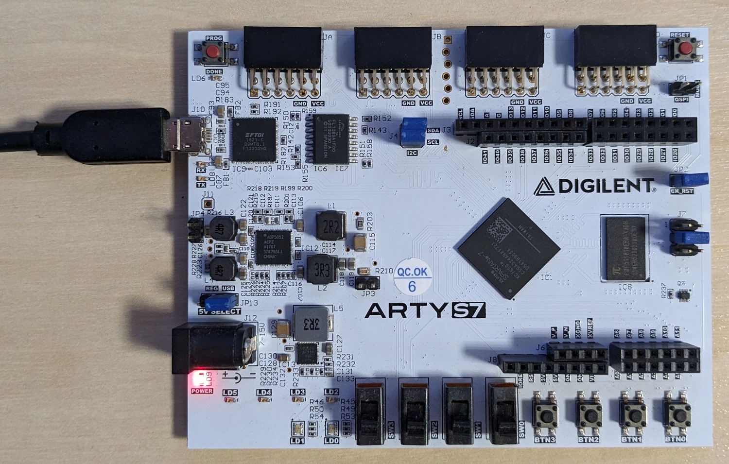
To demonstrate, how easy is to measure a clock signal using Quick Instruments, let's see the whole process for the Digilent ARTY-S7 board.
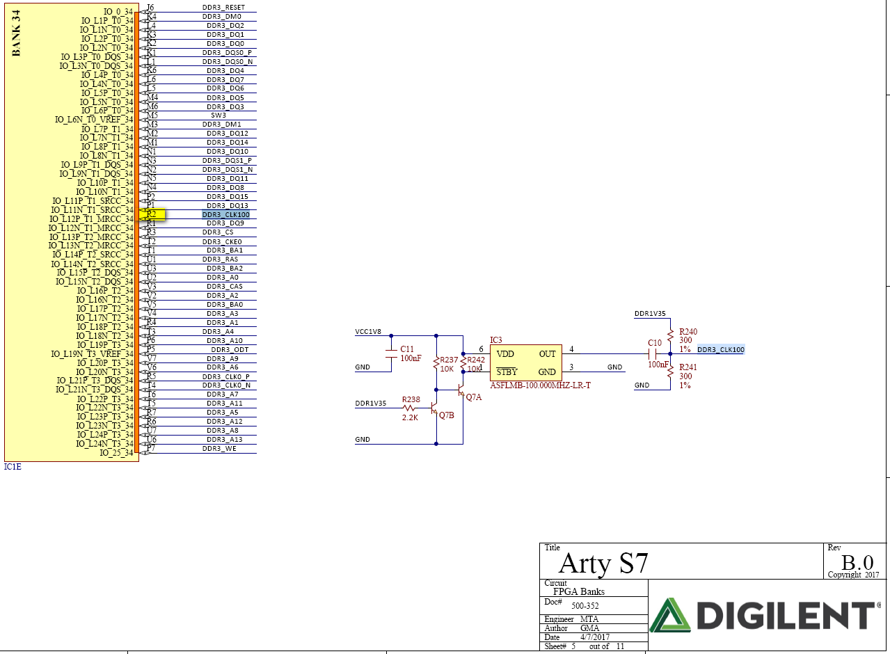
Naturally, you need to start with the board’s schematic and check the pin map between the oscillator(s) and the FPGA. Depending on the complexity of the board, there could be many clock lines on a board, or as in this case, just one coming from the oscillator IC3. The clock line 'DDR3_CLK100' goes to pin #R2 of AMD/Xilinx Spartan-7 FPGA.
All our instruments are pre-developed and can be fetched from the off-the-shelf instrumentation library. Still, we must adapt them for a particular board under test (to achieve optimal performance) and then compile them using our back-end compilation servers.
For the ARTY-S7 board, the information will be the following:
As a response, you get the QI instrument = test firmware in the form of a compiled FPGA bitstream file.
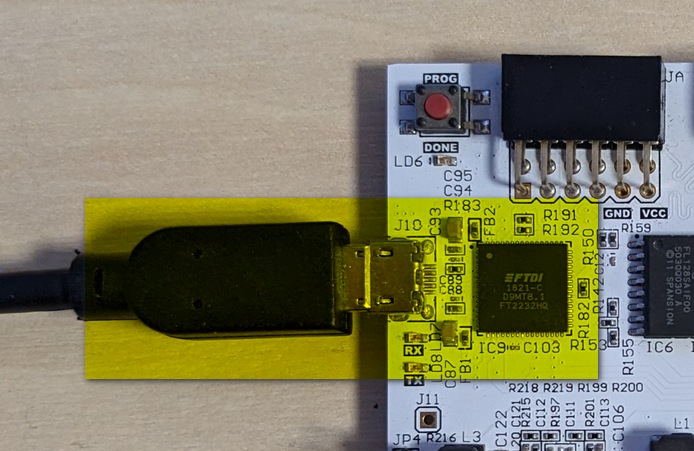
The physical communication between a tester PC and QI firmware running on the board is done via the JTAG bus. The JTAG is used for uploading firmware, communicating with instruments, and fetching the results back to the tester PC.
Some boards, like ARTY-S7, contain the embedded Digilent USB-to-JTAG IC. In this case, you don't need to use an external JTAG cable and you can establish the communication using a standard micro-USB cable.
We recommend writing a test program using a Python scripting language. There is no need to compile a source code, the language is general-purpose and dynamic, thus memory management is handled automatically. Python is widely used and contains many modules that can extend its usability and applicability.
The Python code for the clock measurement on the ARTY-S7 board is simple and straightforward:
driver = TestbusController('Digilent') #Define the JTAG controller
testbus = Testbus(['IC1:xc7s50_csga324'], driver) #specify the JTAG bus
testbus.IpLibrary = 'ARTY-S7.ipl'  #The FW received from us at step 2

if testbus.Check(): #verify JTAG bus communication
      freq = Frequency(testbus) #Instantiate the instrument
      value = freq.Measure('IC1.#R2', System.Int64(0)) #Measure CLK

      driver.Close() #Clean-up
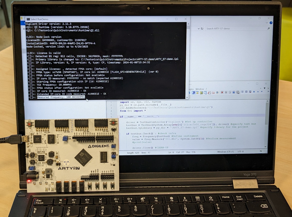
The easiest way to execute the code is to run it in the Command Line Interface: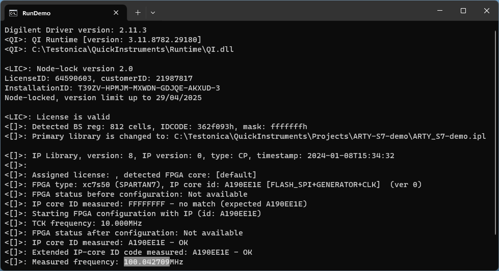
Look at this! The real measurement is done with just one line of code,
value = freq.Measure('IC1.#R2', System.Int64(0)) #Measure CLK
within one second, and using only a USB cable.
No probes, and no complex external equipment! Simple, yet very useful!
Do you also have the ARTY-S7 board? Download the QI Runtime Demo version and try it yourself.
Want to try the QI Frequency Counter and measure CLK lines on your FPGA board? Contact us and we will provide the demo instrument free of charge.